Peak Voltage Detector for a Sine Wave Generator
Contents
I recently built a 1 kHz sine wave generator with adjustable amplitude. It works great and is well suited for testing and repairing audio amplifiers. I thought it would be nice to fit a small panel voltmeter that shows the output voltage.
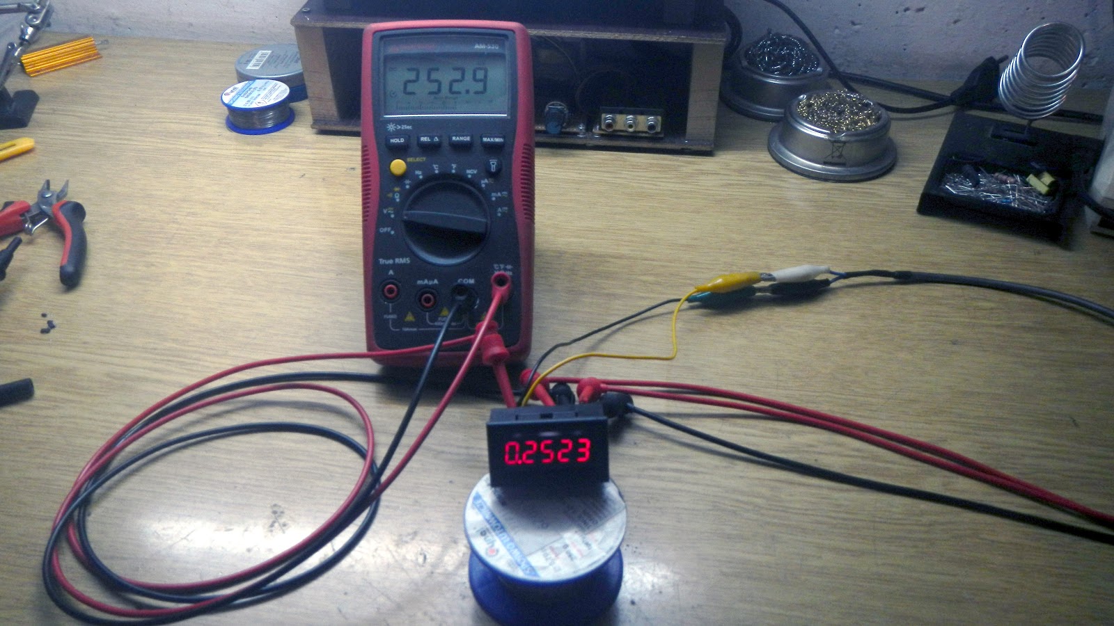
Repairing the panel voltmeters
I bought five panel voltmeters on eBay, and two of them soon stopped working. I decided to find out what had happened to them and fit one of them into the generator.
The 3.6 V voltage regulator on the voltmeter had blown. I removed it and soldered a wire in place of its output pin, then fed 3.6 V through that wire. The voltmeter came back to life.
Peak voltage detector
That was not the end of it. This kind of voltmeter only measures DC voltage, so the sine wave first has to be converted to DC. The best way to do that is with a peak voltage detector, and a µA741 op-amp is all it takes.
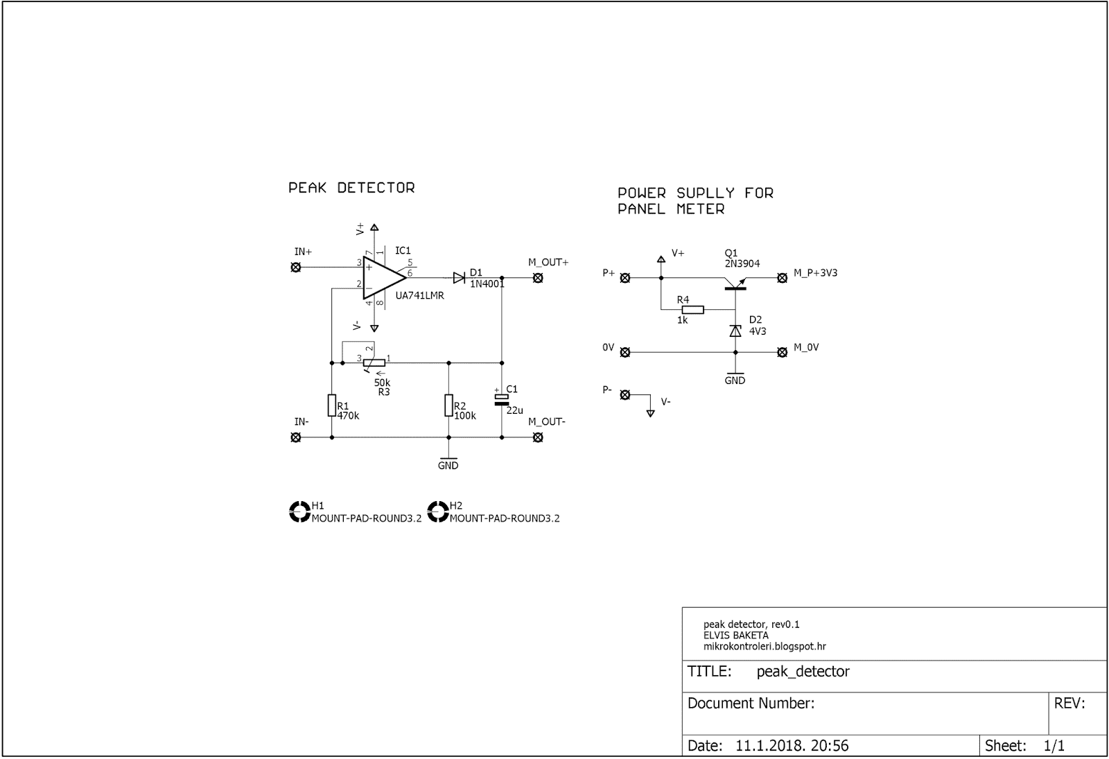
The op-amp charges capacitor C1 (22 µF) through diode D1 to the peak value of the input voltage. The feedback is taken from the capacitor rather than from the op-amp output, so the voltage drop across the diode does not affect the result. Trimmer R3 sets the gain and so calibrates the reading. Resistor R2 (100 kΩ) slowly discharges the capacitor (the time constant is about 2 s), so the reading also follows a falling amplitude.
Voltmeter supply
In place of the blown regulator, the voltmeter is powered by a simple regulator built from a 2N3904 transistor and a 4.3 V Zener diode. The voltage at the transistor’s emitter is about 0.7 V below the Zener voltage, roughly 3.6 V.
Limitation
The device works well but has one limitation: it only measures the positive peak. I will leave it as it is for now, and in the future I plan to build a circuit that measures both the positive and the negative peak.